There are a lot of articles out there on Arduino but today the article which we’ve written is about the Arduino hardware design. Mastering yourself in Arduino hardware is just like you are taking yourself in Arduino to the next level. Understanding Arduino hardware design can also help you in “what you can enter and what you can delete”.
Components Synopsis
Basically, the Arduino UNO’s PCB design uses the SMD components. SMD abbreviation is (Surface Mount Device). There are some kits that are universal and can be utilized for various sections along with various purposes. You know, the measurement of several capacitors, LED, and SMD resistors are marked by kits such as the following…

We are mentioning the list below that will show some of the segments in the Arduino UNO according to their every kit:
Parts | Package |
ATmega16U2-MU | MLF32 |
LP2985-33DBVR 3.3V regulator | SOT753/SOT23-5 |
LMV358IDGKR dual channel amplifier | MSOP08 |
NCP1117ST50T3G 5V regulator | SOT223 |
FDN340P P-channel MOSFET transistor | SOT23 |
M7 diode | SMB |
Synopsis of Arduino UNO system
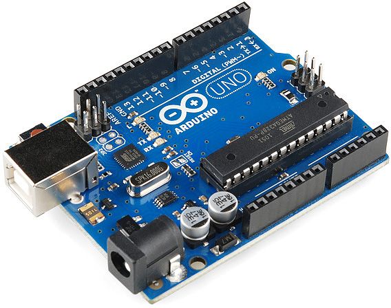
The Arduino UNO system is very easy to understand. It needs just a little bit attention. But before going deep in Arduino UNO, let’s start a little review on it.
When you compile the code, it is transferred to the microcontroller of the Arduino UNO via USB connector. We use the USB connector (Atmega 16U2, consist of USB transceiver and also consist of UART interface) because microcontroller doesn’t exist the USB transceiver that why we need a kind of link that can easily convert the signals among the UART interface of the microcontroller and the host USB signals.
Important points:
- For powering up your Arduino UNO board, you can easily utilize the USB as a power source.
- Don’t worry, you can also utilize the DC jack and USB but how? We’ll discuss it later.
Do you know how to reset your Arduino UNO Board?
Yes right, one source is that you just push a button that exists on the Arduino UNO board and the other is disclosing your serial monitor via Arduino IDE. We’re moving forward but do you know
What is Microcontroller?
We’ve already mentioned “What is microcontroller” in our recent blogs. Let’s take a glance again. Basically, the microcontroller executes the directions or instructions which you have given in your program. The microcontroller ATmega 328 is MCU and used in Arduino UNO R3 that plays a role of “Main Controller” and is from AVR family. The ATmega 328 is an 8-bit device.
Hint: Why ATmega 328 is 8-bit?
Answer: Because the internal registers and data-bus construction are basically manufactured to grasp 8 equidistant data signals. The ATmega 328’s memory is divided into 3 categories.
- SRAM Memory = 2KB volatile memory
- Flash Memory = 32KB non-volatile memory
- EEPROM memory = 1KB non-volatile memory
Point to remember: The ATmega 168 is approximately similar to ATmega 328. They are pinning consonant. The only discrepancy among them is ATmega 328 bear 32KB flash, 1KB EEPROM and 2KB RAM and ATmega 168 has 16KB memory flash, 512 bytes EEPROM, and 1KB RAM. Below, we have also mentioned the Arduino Uno R3 Pinout. Watch it carefully.

Microcontroller Unit’s Specifications:
TWI:
TWI means the two wire interface. It consists of two wires, serial lock, and the serial data: SDA, SCL. The best path for reaching these pins via the last two pins pin 4 and pin 5 that exist in the header section.
Here you can see the Arduino Uno r3 schematic: https://www.arduino.cc/en/uploads/Main/arduino-uno-schematic.pdf
ADC inputs:
ADC means Analog-to-Digital Converter. Basically microcontroller unit has 6 channels from PORTC0 to PORTC5 along with 10-bit resolution A/D converter. All the pins from PORTC0 to PORTC5 are associated with an analog header on the Arduino Board. The mistake we commonly do is: We take analog as assigned input for A/D function only in the act of header in the boards' states “Analog”. This is wrong. The fact is you can utilize them just as digital I/O or A/D.

Power:
Inherently, the microcontroller unit provides voltage from 1.8 to 5.5. Nonetheless, there are a lot of limitations on the operating systems. For example, if you want to max the clock frequency (20-MHz), you demand will be “to supply the voltage of somewhat 4.5”.
Learn the Arduino Uno Programming here: https://www.arduino.cc/en/Guide/HomePage
Packages:
The MCU is available in two different packages TQFP – 32 and DIP – 28. The DIP – 28 packages present Dual-In-Line Package which consists of 28 pins. Majority pins in it are flexible. It lessens the decisive pins. One of the best features of DIP – 28 is that you can easily make your design malleable. It is just because one I/O connection can cater to multiple varieties of functions.

Digital I/O:
This microcontroller unit consists of three ports: PORTB, PORTC, and PORTD. You can utilize these pins for your ordinary purpose digital I/O as an alternative, you can also use it for activities marked in the chart below such as PORTC pin0 to pin5 could be ADC (Analog-to-Digital) inputs rather of digital I/O.
There are some types of pins that could be configured as PWM (Pulse Width Modulation) output. These particular pins are pointed with “~” on the Arduino Board.

UART Peripheral:
A Universal Asynchronous Receiver/Transmitter or majority it is known as UART is a kind of serial interface. The ATmega 328 has one UART module. The UART’s pins (RX, TX) are hooked up with USB-to-UART converter and also hooked up with pin0 and pin1 in digital header.
Important Point: Fend off (Avoid) yourself by using the UART, if you are using it for sending and receiving for data by USB.
SPI Peripheral:
The Serial Peripheral Interface which is also known as SPI Peripheral is also a kind of serial interface. In ATmega 328, it is only one. We know you will use this peripheral as a serial interface, but you know, it can program the MCU alone like a programmer. If you want to reach to the pins of SPI from the header which is next to the MCU in the Arduino Board or from the digital header are mentioned below:
11 <-> MOSI
12 <-> MISO
13 <-> SCK
To be Continued...