


 USB Cable for Arduino UNO, Mega Cable 1.5m
 8 Bit Digital LED Display Module TM1638 Driver Board Wi...
 RGB LED Module Common Cathode Full Colour Red Green Blu...
 Universal PIC Microcontroller Programmer Adapter Board ...
 Vibration Sensor Module for Arduino Electronic Brick Sh...
") DT830B Digital Multi Meter – Compact Measuring Tool F...
DT830B Digital Multi Meter – Compact Measuring Tool F...
 _ 2.4G 25dBm 802.11b /g /n Transceiver _ High Power Stable IoT Board") ESP8266 ESP-06 Serial WiFi Wireless Module (Chip) _ 2.4...
ESP8266 ESP-06 Serial WiFi Wireless Module (Chip) _ 2.4...
") Arduino Nano V3.0 (Economy)
Arduino Nano V3.0 (Economy)
 Arduino Pro Mini 328 - 3.3V/8MHz
 UNO R3 Mega328P CH340G SMD Development Board with Pin H...
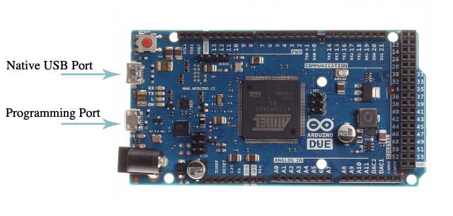
Arduino due
Description:â The Due is Arduino's first ARM-based Arduino improvement board. This board depends on a ground-breaking 32bit CortexM3 ARM microcontroller made programmable through the natural Arduino IDE.
Description:â The Due is Arduino's first ARM-based Arduino improvement board. This board depends on an intense 32bit CortexM3 ARM microcontroller made programmable through the well-known Arduino IDE. It expands the registering power accessible to Arduino clients keeping the dialect as perfect as could be expected under the circumstances with the goal that numerous projects will be relocated in only minutes!
The Arduino Due has 54 computerized input/yield pins (of which 12 can be utilized as PWM yields), 12 simple information sources, 4 UARTs (equipment sequential ports), a 84 MHz clock, a USB-OTG fit association, 2 DAC (advanced to simple), 2 TWI, a power jack, a SPI header, a JTAG header, a reset catch and an eradicate catch. There are likewise some cool highlights like DACs, Audio, DMA , a trial performing multiple tasks library and that's only the tip of the iceberg.
To gather code for the ARM processor, you'll require the most recent rendition of the Arduino IDE: v1.5 (After a time of testing and investigating this will supplant the 1.0.1 IDE inside and out)
In light of the restrictions of framework voltage forced by the Atmel SAM3X8E, Arduino shields that depend on the 5v models won't work appropriately. Every one of the shields that completely actualize the Arduino R3 design are good straight away (like the Arduino WiFi shield and Ethernet Shield) yet different shields probably won't be perfect. Be watchful when you're connecting stuff!
Note:â Unlike other Arduino sheets, the Arduino Due board keeps running at 3.3V. The most extreme voltage that the I/O pins can endure is 3.3V. Giving higher voltages, as 5V to an I/O stick could harm the board.
Features:
- Microcontroller: AT91SAM3X8E
- Operating Voltage: 3.3V
- Recommended Input Voltage: 7-12V
- Min-Max Input Voltage: 6-20V
- Digital I/O Pins: 54 (of which 12 provide PWM output)
- Analog Input Pins: 12
- Analog Outputs Pins: 2
- Total DC Output Current on all I/O lines: 130 mA
- DC Current for 3.3V Pin: 800 mA
- DC Current for 5V Pin: 800 mA
- Flash Memory: 512 KB all available for the user applications
- SRAM: 96 KB (two banks: 64KB and 32KB)
- Clock Speed: 84 MHz
Documents:
Rs. 10216
Product Discount 12,770.00

 _ 2.4G 25dBm 802.11b /g /n Transceiver _ High Power Stable IoT Board")

")


 with USB Cable")

 GPS Module NEO 6MV2 With competible Flight Control EEPROM APM2 APM2.5 Antenna 3.3V 5V Microcontroller Navigation Board")
