

")
 USB Cable for Arduino UNO, Mega Cable 1.5m
 8 Bit Digital LED Display Module TM1638 Driver Board Wi...
 RGB LED Module Common Cathode Full Colour Red Green Blu...
 Universal PIC Microcontroller Programmer Adapter Board ...
 Vibration Sensor Module for Arduino Electronic Brick Sh...
") DT830B Digital Multi Meter – Compact Measuring Tool F...
DT830B Digital Multi Meter – Compact Measuring Tool F...
 _ 2.4G 25dBm 802.11b /g /n Transceiver _ High Power Stable IoT Board") ESP8266 ESP-06 Serial WiFi Wireless Module (Chip) _ 2.4...
ESP8266 ESP-06 Serial WiFi Wireless Module (Chip) _ 2.4...
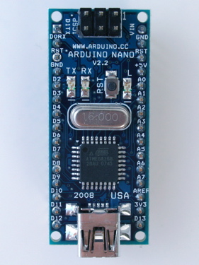
") Arduino Nano V3.0 (Economy)
Arduino Nano V3.0 (Economy)
 Arduino Pro Mini 328 - 3.3V/8MHz
 UNO R3 Mega328P CH340G SMD Development Board with Pin H...
Arduino nano v3.0 with USB cable (Best Quality)
The Arduino Nano is a little, entire, and breadboard-accommodating board dependent on the ATmega328 (Arduino Nano 3.0) orATmega168 (Arduino Nano 2.x).
Arduino Nano:
Overview
The Arduino Nano is a little, total, and breadboard-accommodating board dependent on the ATmega328 (Arduino Nano 3.0) orATmega168 (Arduino Nano 2.x). It has pretty much a similar usefulness of the Arduino Duemilanove, yet in an alternate bundle. It needs just a DC control jack, and works with a Mini-B USB link rather than a standard one. The Nano was planned and is being delivered by Gravitech.
Specifications:
| Microcontroller | Atmel ATmega168 or ATmega328 |
| Operating Voltage (logic level) | 5 V |
| Input Voltage (recommended) | 7-12 V |
| Input Voltage (limits) | 6-20 V |
| Digital I/O Pins | 14 (of which 6 provide PWM output) |
| Analog Input Pins | 8 |
| DC Current per I/O Pin | 40 mA |
| Flash Memory | 16 KB (ATmega168) or 32 KB (ATmega328) of which 2 KB used by bootloader |
| SRAM | 1 KB (ATmega168) or 2 KB (ATmega328) |
| EEPROM | 512 bytes (ATmega168) or 1 KB (ATmega328) |
| Clock Speed | 16 MHz |
| Dimensions | 0.73" x 1.70" |
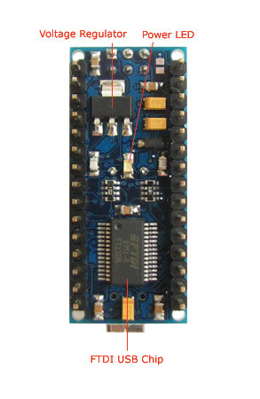
Power:
The Arduino Nano can be fueled by means of the Mini-B USB association, 6-20V unregulated outside power supply (stick 30), or 5V directed outer power supply (stick 27). The power source is naturally chosen to the most astounding voltage source.
The FTDI FT232RL chip on the Nano is just controlled if the board is being fueled over USB. Subsequently, when running on outside (non-USB) control, the 3.3V yield (which is provided by the FTDI chip) isn't accessible and the RX and TXLEDs will gleam if computerized pins 0 or 1 are high.
Memory
The ATmega168 has 16 KB of blaze memory for putting away code (of which 2 KB is utilized for the bootloader); the ATmega328has 32 KB, (likewise with 2 KB utilized for the bootloader). The ATmega168 has 1 KB of SRAM and 512 bytes of EEPROM (which can be perused and composed with the EEPROM library); the ATmega328 has 2 KB of SRAM and 1 KB of EEPROM.
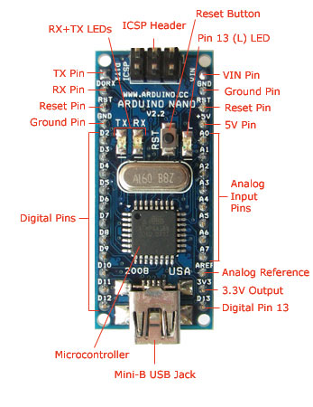
Input and Output
Every one of the 14 computerized sticks on the Nano can be utilized as an information or yield, utilizing pinMode(),digitalWrite(), anddigitalRead() capacities. They work at 5 volts. Each stick can give or get a most extreme of 40 mA and has an interior draw up resistor (detached as a matter of course) of 20-50 kOhms. Furthermore, a few pins have specific capacities:
Sequential: 0 (RX) and 1 (TX). Used to get (RX) and transmit (TX) TTL sequential information. These pins are associated with the comparing pins of the FTDI USB-to-TTL Serial chip.
Outside Interrupts: 2 and 3. These pins can be designed to trigger a hinder on a low esteem, a rising or falling edge, or an adjustment in esteem. See the attachInterrupt() work for points of interest.
PWM: 3, 5, 6, 9, 10, and 11. Furnish 8-bit PWM yield with the analogWrite() work.
SPI: 10 (SS), 11 (MOSI), 12 (MISO), 13 (SCK). These pins bolster SPI correspondence, which, in spite of the fact that given by the basic equipment, isn't presently incorporated into the Arduino dialect.
Driven: 13. There is a work in LED associated with computerized stick 13. At the point when the stick is HIGH esteem, the LED is on, when the stick is LOW, it"s off.
The Nano has 8 simple sources of info, every one of which gives 10 bits of goals (i.e. 1024 distinct qualities). As a matter, of course, they measure from ground to 5 volts, however, is it conceivable to change the upper end of their range utilizing theanalogReference() work. Furthermore, a few pins have specific usefulness:
I2C: 4 (SDA) and 5 (SCL). Bolster I2C (TWI) correspondence utilizing the Wire library (documentation on the Wiring site).
There are two or three different sticks on the board:
AREF. A reference voltage for the simple sources of info. Utilized with analogReference().
Reset. Convey this line LOW to reset the microcontroller. Commonly used to add a reset catch to shields which hinder the one on the board.
-
Communication
The Arduino Nano has various offices for speaking with a PC, another Arduino, or different microcontrollers. The ATmega168 and ATmega328 give UART TTL (5V) sequential correspondence, which is accessible on computerized pins 0 (RX) and 1 (TX). A FTDI FT232RL on the board channels this sequential correspondence over USB and the FTDI drivers (included with the Arduino programming) give a virtual com port to programming on the PC. The Arduino programming incorporates a sequential screen which enables straightforward printed information to be sent to and from the Arduino board. The RX and TX LEDs on the board will streak when information is being transmitted by means of the FTDI chip and USB association with the PC (however not for sequential correspondence on pins 0 and 1).
A SoftwareSerial library considers sequential correspondence on any of the Nano"s advanced pins.
The ATmega168 and ATmega328 likewise bolster I2C (TWI) and SPI correspondence. The Arduino programming incorporates a Wire library to streamline utilization of the I2C transport; see the documentation for subtle elements. To utilize the SPI correspondence, it would be ideal if you see theATmega168 or ATmega328 datasheet.
Programming
The Arduino Nano can be customized with the Arduino programming (download). Select "Arduino Diecimila, Duemilanove, or Nano w/ATmega168" or "Arduino Duemilanove or Nano w/ATmega328" from the Tools > Board menu (as indicated by the microcontroller on your board). For subtle elements, see thereference and instructional exercises.
The ATmega168 or ATmega328 on the Arduino Nano comes preburned with a bootloader that enables you to transfer new code to it without the utilization of an outer equipment developer. It conveys utilizing the first STK500 convention (reference, C header records).
You can likewise sidestep the bootloader and program the microcontroller through the ICSP (In-Circuit Serial Programming) header; see these directions for points of interest.
Automatic (Software) Reset
Or maybe than requiring a physical press of the reset catch before a transfer, the Arduino Nano is planned in a way that enables it to be reset by programming running on an associated PC. One of the equipment stream control lines (DTR) of theFT232RL is associated with the reset line of the ATmega168 or ATmega328 by means of a 100 nanofarad capacitor. At the point when this line is attested (taken low), the reset line drops sufficiently long to reset the chip. The Arduino programming utilizes this ability to enable you to transfer code by essentially squeezing the transfer catch in the Arduino condition. This implies the bootloader can have a shorter timeout, as the bringing down of DTR can be very much organized with the beginning of the transfer.
This setup has different ramifications. At the point when the Nano has associated with either a PC running Mac OS X or Linux, it resets each time an association is made to it from programming (by means of USB). For the accompanying half-second or somewhere in the vicinity, the bootloader is running on the Nano. While it is customized to overlook twisted information (i.e. anything other than a transfer of new code), it will block an initial couple of bytes of information sent to the board after an association is opened. On the off chance that a draw running on the load up gets one-time setup or other information when it first begins, ensures that the product with which it conveys holds up a second in the wake of opening the association and before sending this information.


