

 26p Cable GPIO Expansion line for Raspberry Pi
") Interface Base Board Serial Transceiver Bluetooth Modul...
Interface Base Board Serial Transceiver Bluetooth Modul...
 Pitch FFC FPC TTL Ribbon Flat Cable Reverse Direction") 30 Pin 0.5mm 60mm (6CM) Pitch FFC FPC TTL Ribbon Flat C...
30 Pin 0.5mm 60mm (6CM) Pitch FFC FPC TTL Ribbon Flat C...
 Serial Transceiver Bluetooth Module For Arduino HC-06 07 09") Interface Base (Just Board) Serial Transceiver Bluetoot...
Interface Base (Just Board) Serial Transceiver Bluetoot...
 Raspberry Pi 3 Shell Case Compatible with Fan Robust
 USB Type C with Power switch line Type-c interface 5V 3...
 GPIO U-shaped Adapter Plate V2 Expansion Board Breadboa...
 Raspberry Pi 3 Shell Case Compatible with Fan Robust
 84x48 LCD Display PCD8544 Module for Nokia 5110 Raspber...
 Clear Acrylic Case for Raspberry Pi B+
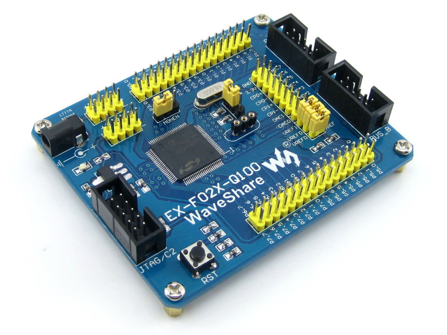
C8051F020 C8051F development board EX-F02x-Q100
A development board for the C8051F02x series microcontrollers, such as C8051F020, C8051F022. It is designed to give designers a quick start to develop code on these devices. This development board comes with the C8051F020 chip in TQFP100 package
Overview

A complete starter kit and development system for theC8051F02x series microcontrollers, such as C8051F020, C8051F022. It is designed to give designers a quick start to develop code on these devices.
This development system contains a main development board with the C8051F020 chip in TQFP100 package, and an additional expansion board with various peripheral devices.
The BUS-A & BUS-B headers located on both boards should be used to connect the two boards via 10-pin cables, which are delivered with the product. As shown in the figure right.
What's On Board
EX-F02x-Q100
- Power
- Powered from 5V DC jack using an onboard 3.3V regulator AMS1117
- Power input/output pin headers
- spare power input port
- convenient for providing power supply to other board/device if necessary
- Onboard Chips
- C8051F020 (TQFP100), the C8051F Microcontroller
- AMS1117-3.3, on board regulator
- Interfaces
- JTAG/C2 port for programming/debuging
- BUS-A & BUS-B, for connecting to the expansion board DVK501, ease to study/develop various peripheral devices
- Human to Machine Interface
- Reset button, used to reset the system
- Power indicator LED
- Other Features
- VDD Monitor enable/disable jumper connected to the MONEN pin
- AD/DA voltage reference jumper
- External crystal configurable
- there is a jumper for selecting on board 16M crystal or custom crystal mounted via the socket
- All the MCU pins are accessible on expansion connectors for further expansion
- All the pins are clearly marked on the PCB. These marks provide the basic information on the pins

- 5V DC jack
- default power input
- Power indicator
- On board regulator
- 3.3V
- AMS1117-3.3
- 10-pin JTAG/C2 port
- Reset
- Microcontroller
- C8051F020
- TQFP100 package
- Pin headers connected to MCU pins
- marked clearly on the PCB
- easy for testing and further expansion
- AD/DA voltage reference
- BUS-A & BUS-B expansion ports
- for connecting to DVK501
- header pinout definition is provided
- ease to develop various peripherals
- External crystal configuration
- on board 16M crystal
- custom crystal socket
- selected via jumper
- VDD monitor enable/disable jumper
- Power input/output
- 5V/3.3V
- spare power input
- power output is available

DVK501
| Device on board | Description | Interface |
|---|---|---|
| AT24CXX | 2-Wire Serial EEPROM keeps data after power down | I2C |
| PCF8563 | Real-time clock/calendar, low backup current from battery | I2C |
| PCF8591 | 8-bit A/D and D/A converter, four channels AD conversion, one channel DA conversion | I2C |
| PCF8574 | Remote 8-bit I/O expander | I2C |
| DS18B20 | Programmable Resolution 1-Wire Digital Thermometer, measures temperatures from –55°C to +125°C | 1-Wire |
| DS2401 | Silicon Serial Number, a low-cost, electronic registration number that provides an absolutely unique identity | 1-Wire |
| AT45DBXX | Serial-interface sequential access Flash memory ideally suited for higher memory density requirement | SPI |
| 74HC164 | 8-bit serial-in, parallel-out shift register, for reducing the IO cost | SART |
| 74HC165 | 8-bit parallel-in, serial out shift register, for reducing the IO cost | SART |
| MAX3232 | 3.0V to 5.5V, True RS-232 Transceivers, for communicating with the PC | serial |
| MAX485 | RS-485 Transceiver, for long distance communication | serial |
| PS/2 | PS/2 interface, for connecting the keyboard or mouse | 2 wires |
| LED | 8-bit status indicator LED, also can be used for displaying simple data | 8 wires |
| Character LCD Connector | Used for connecting the character LCD module, such as LCD1602 | 7 wires or 11 wires |
| Graphic LCD Connector | Used for connecting the Graphic LCD module, such as LCD12864 | SPI or 12 wires |
Examples
Examples that come with this development system will show you how to connect the C8051F microcontroller to other peripheral components or devices and how to develope your prototype device easily. The pictures below show how the EX-F02x-Q100 works with the DVK501 and the results of the examples.
Note: The LCD12864 is not included in the price, please browse our store to buy it separately if you need one. Click on the image to enlarge.
This development board supports 3.3V LCD ONLY.
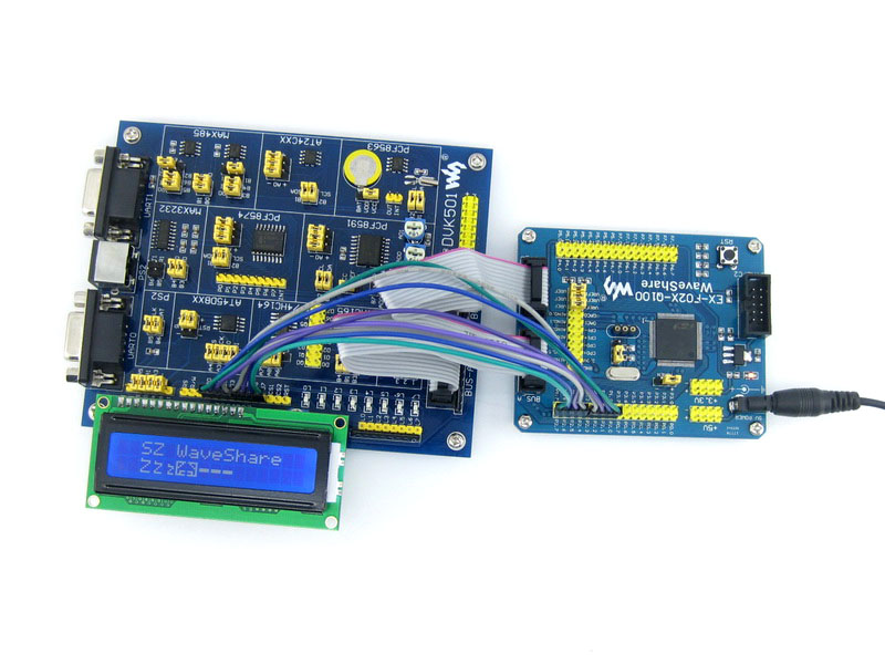
Displaying text on LCD
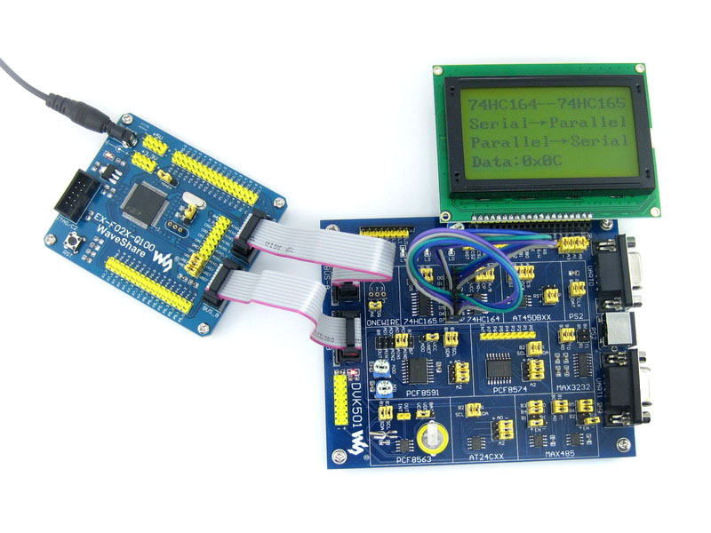
Serial/parallel communication example using 74HC164/74HC165
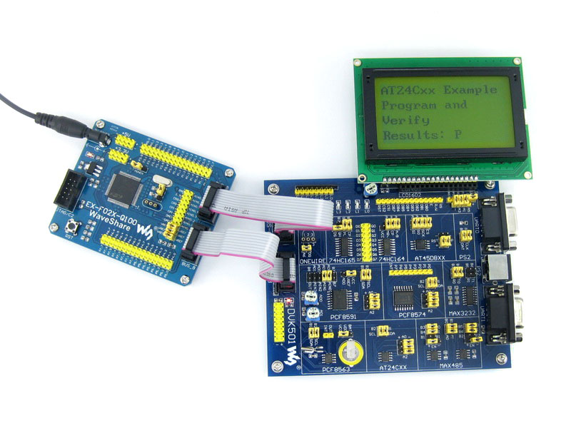
Writing and Reading data from AT24CXX EEPROM via I2C interface
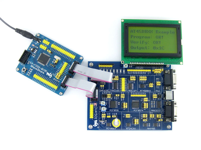
Writing and Reading data from AT45DBXX DATAFLASH via SPI interface
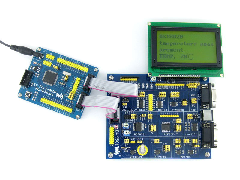
Measuring temperature with DS18B20+ and displaying results on LCD
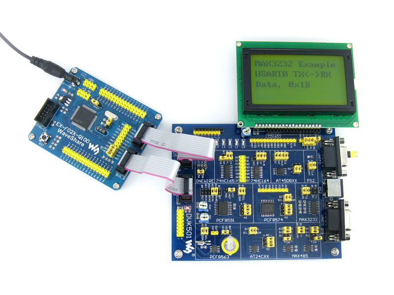
Sending and receiving data over UART interface using MAX3232

Reading date and time from PCF8563 Real Time Clock
Example of PCF8574 I/O expander

A/D conversion and displaying conversion results on LCD
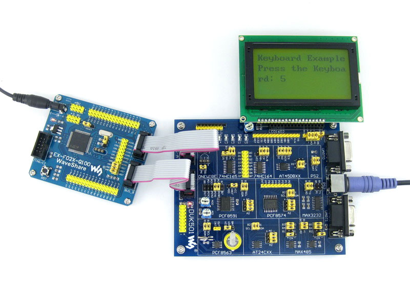
Sending data from PS/2 keyboard
Sending and receiving data over UART interface using MAX485
registration number identification via 1-wire bus using DS2401
Development Resources
- User Guide CD
- CD with software, drivers and examples
- Schematic Circuit Diagram
- Examples in C
- Based on Silabs IDE and Keil
- Related Software
- Silabs IDE
- Keil
- Datasheets of the chips
EX-F02x-Q100 Package
- EX-F02x-Q100
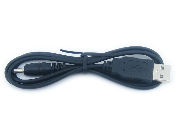
- USB power cable
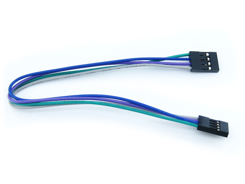
- 4-pin wire x 2
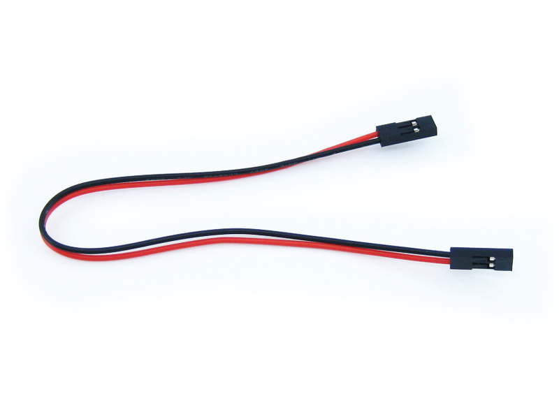
- 2-pin wire x 2
- User Guide CD


Micro Memory SD Card For Raspberry Pi")
")

